MSc thesis project proposal
Bio-inspired air flow sensor for micro air vehicles
Technological advances in microfabrication technologies can drive new applications such as autonomous micro air vehicles (MAV), small autonomous flying drones that can have a major impact on civilian tasks, including communications, greenhouse agriculture, building inspection and disaster relief.
Among the different type of MAV’s, the flapping wing devices are the smallest and lightweight type of aircrafts, and perhaps more bio-inspired compared with rotor type or fixed wing devices.
However, autonomous flying, specifically for sub-10 g devices poses major scientific and engineering challenges due to the energetic cost of staying in the air; furthermore, efficient flight control requires larger number of sensors with corresponding larger demand for data processing. Unfortunately, with the stringent weight and power requirements of MAVs such advanced on-board sensor systems are often beyond the power/weigh budget.
A solution could lie in the application of intrinsic smart sensors, where the “smartness” is not in the advanced data processing but in the sensor architecture itself. Among the different kind of sensors, an air flow sensor that is integrated on the flapping wing could significantly contribute to a more efficient flight control.
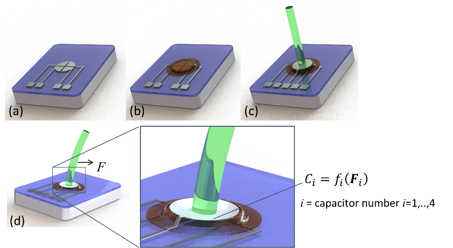
Inspired by biology, the hair sensor concept is considered as potential air flow sensor. The basic operating principle of the sensor is shown in the figure. Using microfabrication technologies, a set of capacitors is fabricated on a free standing ceramic membrane (a-c). On top of the capacitors, a high aspect ratio pillar is attached. A force acting on this pillar will deform the membrane (d) which will change the underlying capacitors and thus producing an electronic signal.
In this project, the layout of the capacitors (area and form) and the dimensions of the pillar needs to be designed such that airspeed data can be obtained with the least possible data processing.
Assignment
- Given the specifications of the read out electronics you define a range of capacitor values
- Build a 3D model of the device as given in figure 1 using materials/ data sets of the materials that are (potentially) applied in the fabrication process
- Couple the 3D model to a suitable multi physics simulator such as ANSIS or COMSOL
- Define a process flow to fabricate the device including a design of experiment in which critical parameters for the capacitors are varied.
- Fabricate the devices in the EKL cleanroom
- Measurements and evaluation
- Reporting
Last modified: 2023-11-07